Seal face width less than 10 of the mean radius. Detailed design calculations are not required in most cases where the application is a typical Plan 23 the mechanical seal contains a well designed circulating device best practices are used for the layout and piping of the loop and a well designed heat exchanger with known performance characteristics is used.

Mechanical Face Seal Kinematic Model And Spiral Groove Geometry Profile Download Scientific Diagram
Mechanical seal design includes static calculations on the seal rings which must have a sufficient factor of safety to avoid bursting.
. The experimental verifications of the single-seated and the double-seated DPR designs with the inlet pressures of 928 698 50 32 MPa have been satisfactory agreed with the calculation. Conditions such as temperature or pressure outside its design envelope can damage the seal and result in greater leakage rates. To simplify we take the OD pressure to be the gauge pressure so the ID pressure is zero.
To calculate the shaft speed that a packing will be exposed to use this. Add approximately 016 to account for the squeeze the bellows must have to seal the shaft. The ratio between packing and mechanical seal leakage rate is 8001 respectively PPc pp1-3.
We offer a complete line of seals including cartridge seals dry-running seals metal bellows elastomeric bellows mixer seals split seals and bearing. To be sure the seal will fit inside the stuffing box bore of the pump. Deans original philosophy included exceeding customer expectations with great.
As was stated earlier it is hoped that the application and design of the mechanical seal is suited for the service. For the Reynolds equation to be satisfied one or more of the following statements must be true. Furthermore packing increases the power requirement by a ratio of 61 when compared with mechanical seals.
0 psi 25 psi 50 psi Liquid Liquid Vapor Vapor Liquid Vapor Pressure Drop Vaporization 100 psi TYPES OF MECHANICAL SEALS SEAL TYPES. A short collection of mechanical seal performance calculations has always been included in the earlier and current editions of the. We have integrated on-line propaganda with off-line propaganda to build brand name recognization.
Swagelok design options include high-point vents in the seal support system allowing systems to be vented and cleared of entrapped air to prevent flow or cooling disruption. Assume that mass leakage approaches zero. Measure the Seal Head ID.
Therefore if you can say that the flush system for an application can provide all the qualities most important is cost. 32 Mechanical Face Seals 1176 33 Emission Concerns 1180 34 Noncontacting Seals for High-SpeedAerospace Applications 1183 35 Labyrinth Seals 1188 36 Honeycomb Seals 1191 37 Brush Seals 1192. Other system factors that affect seal leakage rates besides.
Has established itself as an industry leader in the sealing and gasketing industry. Determine the Working length of the seal. Seal face separation may have parallel converging or diverging leakage paths.
You can calculate the correct length of packing required for a given shaft size by using this. Flowserve seals are the industrys top choice for the most challenging environments. Ad Roxtec is a leading provider of mechanical seal software in the UK.
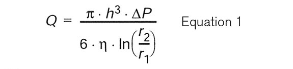
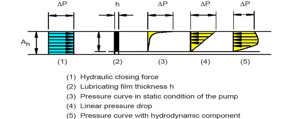
In Equation 2 the pressure gradient factor k is taken as ½. Constant seal face temperature but axial temperature gradients may exist. With the restrictions placed on process industries factories and manufacturers by the.
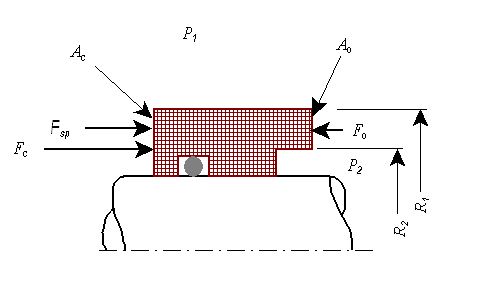
R 1 2698 mm 1062 in r 2 3175 mm 125 in h 0254 μm total surface roughness 10 μin ΔP 18 MPa 265 psi η 10 x 10 3 Pas 145 x 10 7 lbf-secin 2 See Equation 1 for how the theoretical leakage rate of a liquid. The ratio of closing area to opening area is the seal balance B and is also often expressed as a percentage. The softer mechanical seal face usually has a smaller mating surface and is commonly called the wear nose of the mechanical seal.
With the seal face rotating in clockwise direction rotating in clockwise direction L anti clockwise Looking from the stationary seat toward the seal face Looking from the drive side with the shaft with the seal face rotating in anticlockwise direction rotating in anticlockwise direction S independent of direction of rotation. Online tool for designers. Calculations are based on the following assumptions.
Designed for Reliability and Maintenance. Mechanical seals classified by Arrangement. Measure the Spring Free Length.
Mechanical seals classified by Design. The rubber seal joints shall be designed to withstand the design end thrust pressure. Measure the seal head OD.
The PV value is widely used as a guideline for mechanical seal design and application. To calculate the stuffing box pressure a packing will be exposed to in a pump use this. Mechanical Joints or Rubber Seal Joint.
A ro 0 b p 0 c h 0 d 0 e µ 4 For a to be true the seal geometry would cease to exist. Measure the Rotating Units Free Length. This chapter aids the practicing engineer in making an initial seal.
The PV value can be important because it represents both wear and heat generation. Mechanical seal flush must possess the following qualities for optimal seal life it must be cool clean and approximately 345 kPa 50psi above vapor pressure psia and most importantly it must be cost effective. Mechanical seal design calculations We commit ourselves to expand the influence of DMS Seals brand to enhance the enterprise reputation and overall competitiveness.
Seal designs are considered unbalanced or balanced. Seal Design is a leading manufacturer and distributor of die cut gaskets seals o-rings and molded rubber products. Even so it has only a very rough correlation with overall seal performance.
Manufacturers have their own proprietary design of mechanical. Penman Seal Design Inc. Seal faces are flat with isotropic roughness.
It represents the fraction of fluid pressure acting to close the seal. These joints can be either of the screwed or socket type with a locking key and are sealed by means of an O-ring which is compatible with the service fluid. If so there is leakage of only vapor through the seal faces.
A short collection of mechanical seal performance calculationshas always been included in the earlier and current editions of theseal standard API 682 and the co-branded version of ISO 21049The new draft of the Fourth Edition of API 682 and the plannedupdate of ISO 21049 include a significantly expanded version ofthese calculations plus associated. In systems with highly corrosive fluids are recommended mechanical seals with external springs. Approaching a seal design one has a wide range of available seal choices.
Established in 1989 by Dean T. A valid assumption used is that face seal rings behave as hollow cylinders with open ends. Designs also may include low point drains to allow the system to be quickly and safely purged of buffer barrier or flush fluids.
Siewert Equipment is the exclusive provider of Flowserve mechanical seals for Upstate NY.
Calculate The Leakage Rate Of A Mechanical Seal Pumps Systems
1 Seal Mechanical Seal
Energies Free Full Text Multifield Coupling Model And Performance Analysis Of A Hydrostatic Mechanical Seal Html
Pdf Performance Of Centrifugal Mechanical Face Seal
Simple Theory Seal Faqs

Design Supply Sm Seals
An Introduction To The Five Key Features Of Good Mechanical Seal Design Reliability Matters
Calculate The Leakage Rate Of A Mechanical Seal Pumps Systems
0 comments
Post a Comment